


The local controller in a commercial and industrial battery energy storage project is usually the last thing specified and among the first to cause trouble. The battery, inverter and EMS software all get evaluated properly. The box those three converge on tends to get picked from a datasheet comparison: processor, memory and total port count. The mismatch surfaces at commissioning, when the fire panel contact has nowhere to land or the grid meter is sitting eleventh in the queue on the site’s one serial loop.
We build that box, so this is the part of the system we see repeatedly across projects: not what an energy storage system does, but what its controller ends up having to terminate. The pattern is consistent enough to be worth writing down. The requirement for an energy storage EMS controller is set by the function list: what the project is being paid to do, what the controller has to reach and how it connects.
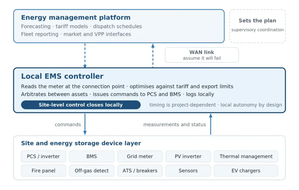
Energy storage EMS controller architecture showing the local controller between field devices and the upstream energy management platform.
Figure 1. The local EMS sits between the device layer and the management platform: it reads the meter at the connection point, decides and commands the equipment around it.
The I/O footprint of an energy storage project
The functions a project is bought for do not all talk to the same equipment, and they do not all arrive over the same medium. Laid out side by side, the interface list stops looking like a datasheet column and starts looking like a consequence.
| What the application does | What it has to reach | How it connects |
|---|---|---|
| Peak shaving and demand-charge management | The meter at the grid connection point | Serial or Ethernet depending on meter class, and ideally not queued behind slower devices |
| Export limiting and anti-backflow | The same meter, plus the power conversion system | A communications path each way, plus whatever fail-safe path or interlock the grid scheme requires |
| Time-of-use and tariff scheduling | Battery state of charge and a synchronized clock | CAN, serial or Ethernet depending on the BMS or controller interface, plus onboard data retention so the schedule survives an outage |
| Grid and island-mode coordination | ATS or microgrid controller, breaker and switch state | Digital inputs and relay outputs for the interlock layer, alongside whatever protocol runs the transfer |
| Fire and safety interlock | The fire detection and suppression panel | Commonly a dry-contact digital input for the interlock, with panel and detector status often carried over a bus as well |
| Thermal management coordination | Cooling units | Serial or Ethernet, commonly Modbus or BACnet depending on the auxiliary controller, usually with dry-contact alarms alongside |
| Adding PV or sub-metering | PV inverters and additional meters | More devices to poll and more ports if they cannot share a segment |
| Multi-cabinet sites | Other cabinets and the upstream platform | Ethernet on a network kept separate from the field side |
Read the middle column and the specification writes itself. A project that only shaves peaks needs far less than one that also limits export, transfers to island mode and coordinates PV. The interfaces are not a feature list; they are the footprint of the functions the customer is paying for.
Two of those rows have written requirements behind them worth having the references for. What gets controlled is what the meter at the connection point sees. One utility’s published scope of work for a battery storage EMS states that the plant should control to the requested MW value “at the Meter Point to within 2% after a 4 second settlement period” and specifies timestamps in UTC synchronized to 1 ms by NTP or GPS.
On the equipment side, IEEE 1547-2018 requires a distributed energy resource to present a local interface supporting at least one of IEEE 2030.5, IEEE 1815 (DNP3) or SunSpec Modbus. Which physical interface that arrives on is a separate question, and the standard leaves it open.
What decides the port count
Serial capacity is not one number
What matters is not how many ports a specification sheet lists but how the devices divide across them. The Modbus serial specification sets the constraints: the bus is single-master and slaves never transmit unrequested, every device on a line must share the same transmission mode and serial port parameters, and 32 devices is the count it always authorizes on a segment without a repeater, with more possible where the transceiver loading and device documentation allow it.
The meter that peak shaving and export limiting both depend on should not be sitting behind a dozen slower devices, and a device that disagrees on baud rate or framing needs a segment of its own. Both push a site toward more segments rather than longer ones: a purchasing decision, not something that can be configured away later.
Some signals stay off the network
Where the fire system has to drive a discrete interlock, a hardwired contact is the common implementation. NFPA 72 Chapter 21 recognizes several means of interconnection to an emergency control function interface device, including electrical contacts listed for the connected load and data communications over a signaling line circuit. Which one applies is a project and authority decision rather than a fixed rule.
Panel and detector status is a separate question and often arrives over a serial bus in the same cabinet. Switch and breaker position is usually brought in as a contact too, for availability rather than accuracy. Whatever the reasoning on the safety side, the consequence for the controller is fixed: those points need real digital inputs and relay outputs, and a box with plenty of Ethernet but no field I/O cannot accept them at all.
Autonomy is an interface requirement too
Where a scheme has to hold a limit through a failure, the requirement is written down. ENA Engineering Recommendation G100 Issue 2 requires a limitation scheme to detect a communication or internal failure and move itself into its failed state within 15 seconds, with a default of one minute to bring an occasional excursion back within the limit.
Read that as a controller requirement. The measurement, decision and command have to stay inside a fail-safe local path. Whether those functions sit on one controller or across several coordinated devices is an architecture decision, and G100 explicitly contemplates schemes built from dispersed components.
Schedule persistence is a separate matter and not something G100 asks for. It comes from the application: a tariff schedule that has to keep running through a WAN outage needs enough onboard data retention to do so, which is a design choice rather than a requirement.
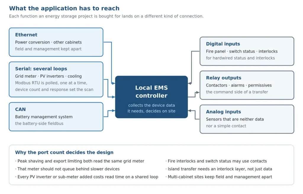
Interface map showing a local EMS controller concentrating Ethernet, serial, CAN, digital I/O and analog signals from devices in a commercial and industrial battery energy storage cabinet.
Figure 2. The same picture from the controller’s side: what the application has to reach determines the interface mix.
When a separate controller is not the answer
This is worth saying plainly because it decides whether any of this applies. On a single-vendor site, the inverter platform often handles export limiting itself, reading a meter at the connection point over its own link. Nothing is gained by adding a controller alongside it.
A separate local EMS, often called a BESS EMS controller, earns its place when the site is mixed-vendor or when the functions stack: export limiting plus demand-charge management plus tariff scheduling plus island transfer plus fire interlock, arbitrated together. That is the point at which the I/O footprint above stops being a list and starts becoming a constraint.
Where NODKA fits
NODKA builds the hardware layer, not the EMS software. Peak shaving, export limiting, tariff scheduling and grid transfer are functions of the EMS application and the system design around it. What the controller provides is the compute, onboard memory and enough of the right interfaces for the functions the project needs. That last part tends to be the one underestimated.
That is what the ABOX-3906 was designed for: an ARM platform with eight isolated RS485 ports rather than one or two, CAN for the battery side, genuine digital inputs and relay outputs for signals that stay off the network, and analog inputs for continuous sensor signals.
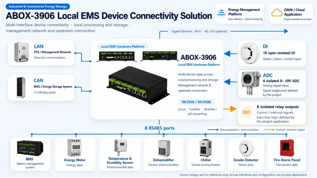
Device connection diagram for a local EMS built on the ABOX-3906, showing the meter, battery management system, power conversion system, cooling, sensors and fire panel terminating on Ethernet, serial, CAN, digital input, relay output and analog input interfaces, with an uplink to the energy management platform.
Figure 3. The same idea as a real device. The field equipment along the lower edge terminates across serial, CAN, digital input, relay output and analog input, while Ethernet carries the uplink to the management platform.
Where a project needs x86 rather than ARM, the NP-6111 series covers the same role. Both platforms are neutral as to software: the EMS application is the integrator’s choice, and NODKA neither supplies nor endorses one.
For a repeatable cabinet design rather than a one-off, NODKA’s OEM/ODM engineering services can match the I/O configuration to the functions a particular project sells.
Key takeaways
- Specify the controller from the function list, not from a datasheet comparison. Each function lands on a different kind of connection.
- Port count usually binds before processor performance does, and how devices divide across segments matters more than the total.
- Where a project uses hardwired interlocks and contact status, the controller needs real digital inputs and relay outputs. Ethernet and serial alone cannot accept them.
- A single-vendor site may not need a separate controller. It earns its place on mixed-vendor sites and where several functions have to be arbitrated together.
Specify a Local EMS Controller
Industrial computing with the interface count an energy storage application actually needs.
The table above reflects NODKA’s experience supplying industrial computing hardware for energy storage projects and describes common patterns rather than requirements. Interface arrangements vary by equipment, project and jurisdiction. Where a hard requirement is cited and a public primary source is available, it is linked at the claim: the Modbus over Serial Line specification; ENA Engineering Recommendation G100 Issue 2 Amendment 2, a British requirement; IEEE 1547-2018, via a U.S. national-laboratory implementation guide; and a scope-of-work exhibit filed by a U.S. utility, whose 2% figure is advisory (“should”) in the original. NFPA 72 Chapter 21 is named without a link because no current-edition public text was available to cite. The applicable standards and grid codes for your installation are the authority. NODKA is an independent industrial hardware manufacturer, is neutral with respect to EMS software and battery vendors, and is not affiliated with any company or standards body named above. Product names and trademarks belong to their respective owners.