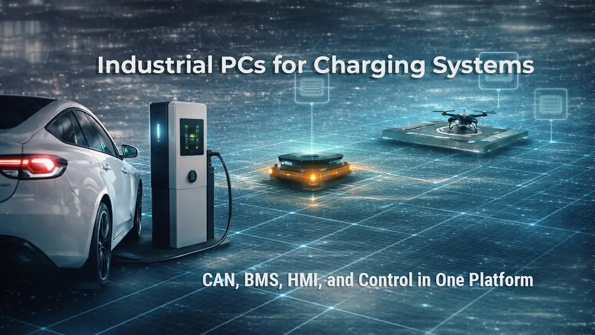
Industrial PCs for Charging Systems: CAN, BMS, HMI, and Control in One Platform
Article Key Points:
- Modern charging systems need smarter, more flexible control.
- CAN remains essential for reliable charging system communication.
- CAN 2.0 and CAN FD support different performance needs.
- Industrial PCs can unify control, communication, and HMI.
- OCPP, diagnostics, and remote access are becoming more important.
- NODKA Automation PCs are built for advanced charging applications.
Modern charging systems are evolving into more intelligent, software-defined platforms. Whether the application is EV charging infrastructure, AGV and AMR charging stations, robot charging docks, drone charging systems, battery cabinets, or other industrial charging systems, the controller is no longer responsible for only basic power sequencing. It must also manage communication, local visualization, subsystem coordination, diagnostics, and often remote connectivity.
For system designers, this raises a bigger architecture question: how do you combine CAN communication, battery management system (BMS) integration, HMI, control logic, and gateway functions without turning the system into a patchwork of separate devices?
This is where industrial PCs are becoming a stronger fit. Compared with simpler controller architectures, an industrial PC can bring CAN-based communication, HMI functionality, higher-level software logic, and system connectivity together on one platform. For charging systems that need both control and computing capability, that can simplify development while creating more room for future expansion.
Why Charging Systems Need More Than Basic Control
In many charging applications, the control platform must coordinate multiple functions at the same time. A modern charging controller is no longer responsible for only turning power on and off. It often sits at the center of the system, linking the charged device, battery-related logic, user interface, and upper-level monitoring environment.
A typical charging architecture may need to coordinate communication with the battery system or the device being charged, internal subsystem control, local HMI operation, diagnostics, event history, and network connectivity to upper-level platforms. This is especially important in charging systems that go beyond simple fixed-function designs. As systems become more intelligent and connected, the controller must act as both a real-time automation node and a higher-level computing platform.
| Charging system function | Why it matters |
|---|---|
| Device or battery communication | Exchanges charging status, limits, and operating data |
| Internal subsystem coordination | Connects power modules, converters, meters, and protection devices |
| HMI and visualization | Gives operators and technicians access to status, alarms, and setup |
| Diagnostics and logging | Supports troubleshooting, maintenance, and event traceability |
| Network and gateway connectivity | Links the charger to site-level or cloud-based management systems |
| Software expansion | Leaves room for future features, updates, and integration work |
The Role of CAN in Charging Systems
CAN remains one of the most practical communication methods in charging system design because it is widely used, electrically robust, and well suited for distributed control architectures. In many charging systems, CAN is used not only for communication inside the charging cabinet but also, depending on the application, for communication with the battery-powered device or vehicle being charged.
For designers building industrial or mobile charging equipment, CAN helps create a modular architecture where devices can exchange control and monitoring data reliably across a shared bus.
Common CAN-based communication tasks include:
- Exchanging voltage, current, and status information with the battery system
- Coordinating charge permissions and operating limits
- Communicating with BMS-related devices
- Linking control boards, power modules, and peripheral units
- Carrying fault, alarm, and operating-state data across the system
A useful way to think about CAN in charging systems is to separate it into two communication layers:
Inside the charging system CAN can link control boards, power modules, meters, protection devices, and BMS-related hardware across the cabinet or charging station.
Between charger and charged device Depending on the charging architecture, CAN may also be used to exchange charging-related data with the battery-powered device or vehicle being charged.
This dual role is one reason CAN remains so relevant in automation-oriented charging systems.
CAN 2.0 and CAN FD: Similar Applications, Different Requirements
Both CAN 2.0 and CAN FD can be used in charging systems, but they are not always chosen for the same reasons. In many real projects, the question is not which one is universally better. The better question is which one fits the communication load, subsystem design, and future roadmap of the charger.
| Criteria | CAN 2.0 | CAN FD |
|---|---|---|
| Best fit | Stable, straightforward communication tasks | Higher-throughput, more data-rich communication |
| Typical use in charging systems | Basic charging-state exchange, standard BMS data, fault reporting | Richer diagnostics, faster updates, more detailed subsystem data |
| Strength | Simplicity, compatibility, proven field use | Larger payloads and more communication headroom |
| Design value | Good for long-lifecycle, well-defined architectures | Better for systems expecting feature growth or more complex data exchange |
Where CAN 2.0 Still Fits
CAN 2.0 remains a practical choice for many charging applications where communication needs are relatively straightforward and deterministic behavior is more important than larger payload sizes. For many industrial charging systems, it still provides a strong balance of simplicity, robustness, and compatibility.
When CAN FD Becomes More Attractive
CAN FD becomes more valuable when the system needs higher throughput, larger data payloads, or more detailed communication between connected devices. This can be useful in charging architectures that require more complex battery or subsystem data exchange, faster update cycles, more data-rich diagnostics, or a more future-ready communication strategy.
In practice, the choice is often not about replacing CAN 2.0 everywhere. It is about selecting the communication layer that best fits the charging system’s performance, integration, and scalability requirements.
Why Use an Industrial PC Instead of PLC
PLCs remain important in industrial automation, especially for deterministic control and straightforward machine logic. But many charging systems require more than scan-based control alone.
The real design decision is often not PC or PLC as a strict either-or choice. Instead, it is about how much of the architecture needs to handle higher-level communication, visualization, diagnostics, and software-defined functions in addition to real-time control.
| Requirement | PLC-only approach | IPC-based approach |
|---|---|---|
| Deterministic control | Strong fit for fixed control logic | Can support this through Soft PLC or hybrid control architectures |
| HMI and visualization | Usually more limited or separated | Easier to integrate rich local or remote HMI |
| Protocol and gateway functions | Often requires added devices or software layers | Easier to consolidate on one platform |
| Logging and diagnostics | Possible, but often narrower in scope | Better suited for richer data handling and service tools |
| Software expansion | More constrained by platform structure | Greater flexibility for future feature growth |
| Open software environments | More limited depending on controller family | Better suited for open software platforms and Soft PLC approaches |
This does not mean PLCs have no role. In some systems, a PLC or dedicated real-time controller may still be used for specific low-level or safety-oriented tasks. But when the system designer wants to combine charging control, communications, HMI, and software-defined features on one platform, an industrial PC often provides a more scalable solution.
Why HMI Matters in Charging System Design
Modern charging systems often require more than indicator lights or minimal local controls. Operators, technicians, and integrators may need access to charging status displays, setup and configuration screens, alarm and fault history, service tools, manual operating modes, and visual diagnostics.
An IPC-based architecture makes it easier to support these interfaces on local touchscreens or industrial display panels. This is especially valuable in industrial charging cabinets, robotic charging stations, and battery service systems where usability and serviceability matter just as much as control logic.
For example, a service technician may need to view battery status, check communication errors, confirm charger states, and access maintenance functions from one screen instead of relying on separate diagnostic tools.
That kind of workflow is much easier to support when HMI is treated as part of the controller architecture rather than as an afterthought.
Why OCPP and Gateway Functions Strengthen the Case for IPCs
In networked charging systems, the controller may also need to connect to higher-level platforms for monitoring, authorization, maintenance, or fleet management. This is where IPC-based architectures often have an advantage.
A more software-capable platform can make it easier to support OCPP or similar backend communication layers, cloud or site-level monitoring, data aggregation and reporting, remote diagnostics and software updates, and integration with broader energy or automation management systems.
For this reason, an industrial PC is not only a charging controller. It can also act as the communication gateway between the charging hardware and the wider operating environment.
In practical terms, this means one platform can coordinate field-level charging logic while also handling the software-facing tasks that make a modern charging system easier to monitor, maintain, and expand.
Open Software Platforms and Soft PLC Architectures
For system designers who want the familiarity of industrial control software with the flexibility of PC-based hardware, open software platforms and Soft PLC architectures can help bridge the gap. Examples in the market may include environments such as CODESYS, depending on the project and software strategy.
These software-driven architectures can support IEC 61131-3 style control logic, open software-defined control structures, communication handling across industrial interfaces, HMI and visualization integration, and easier migration between hardware performance levels.
This is one reason an Automation PC can be attractive when a charging system requires both control behavior and higher-level computing capability. Rather than treating control, interface, and communication as separate hardware layers, developers can consolidate more of the architecture onto a single industrial computing platform.
For NODKA, the key point is not that a specific software package is bundled with the hardware. The value is that the IPC platform gives system designers the flexibility to choose the software environment that best matches their charging application requirements.
Connecting CAN, BMS, HMI, and Control on One Platform
Charging systems increasingly need one controller to coordinate multiple layers of functionality: CAN communication, BMS-related data handling, local HMI operation, higher-level software logic, site or cloud connectivity, and diagnostics with room for future software expansion.
This is where an industrial PC can provide a strong architectural advantage. Instead of separating each function into isolated devices, designers can use one platform to centralize control and improve integration across the charging system.
A useful way to view the architecture is as a layered stack:
- Device and battery communication through CAN or related interfaces
- Control logic for charge sequencing, interlocks, and subsystem coordination
- HMI and visualization for local operation and service access
- Gateway and software functions for logging, OCPP, remote access, and future expansion
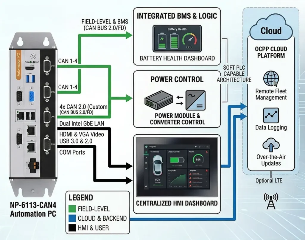
When these layers are brought together on one industrial computing platform, the result is often a cleaner and more scalable controller design.
How NODKA Automation PCs Fit Charging System Architectures
NODKA’s Automation PC portfolio provides a practical fit for charging system control where CAN communication, HMI support, and software flexibility are required.
For more compact controller designs, the NP-6113 fanless Automation PC series can support charging systems that need stable industrial computing, CAN integration, and fanless reliability in cabinet-level deployments.
For applications that require stronger processing performance, richer software headroom, and broader subsystem integration, the NP-6123 / NP-6133 Intel Core-based Automation PC series provide a higher-performance platform for more advanced charging controller architectures.
| NODKA platform direction | Charging-system fit |
|---|---|
| NP-6113 fanless Automation PC series | Compact controller designs needing fanless reliability and CAN integration |
| NP-6123 / NP-6133 Intel Core-based Automation PC series | Higher-performance charging controllers needing more software headroom, richer HMI, and broader subsystem coordination |
| 2 x CAN 2.0 configurations | Suitable for more compact or less segmented charging architectures |
| 4 x CAN 2.0 configurations | Better for systems with multiple CAN-connected subsystems or separated bus domains |
| Custom CAN FD options | Useful where higher-throughput or more advanced communication strategies are required |
In practical terms, this makes the platform suitable for a wide range of charging applications, including EV-related charging systems, industrial battery charging, AGV and AMR charging stations, robotic charging equipment, drone charging systems, and other automation-oriented charging systems where control, communication, and interface functions need to be brought together.
Where projects require higher data throughput or a more advanced communication strategy, custom CAN FD options may also be worth considering as part of a longer-term controller roadmap.
Final Thoughts
Charging systems are evolving into integrated automation platforms that combine device communication, control logic, HMI, diagnostics, and network connectivity. In this environment, the controller must do more than execute basic charging sequences.
Industrial PCs provide a strong foundation for this kind of charging system design. By supporting CAN-based communication, BMS integration, touchscreen HMI, open software flexibility, and higher-level gateway functions, they help system designers build more scalable and more intelligent charging architectures.
For developers evaluating how to unify control and communication in one device,
NODKA’s CAN-enabled Automation PC platforms offer a practical foundation for modern charging system controller design.